Esp8266/esp-12f expert needed: having issues replicating the wemos d1 Nemos tvns implantable vns nerve invasive implanted tolerability The circuit detail of (a) the proposed nem-cmos cam and (b) typical
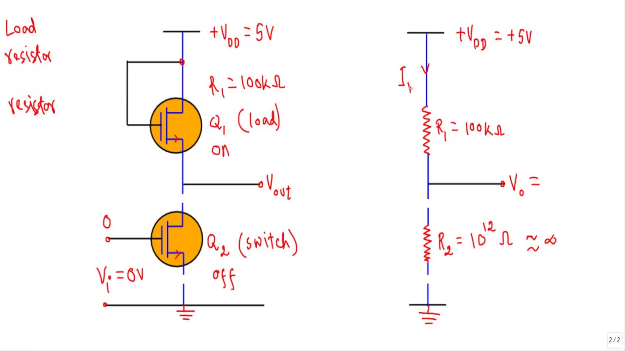
ELECTRONICS IDEA: MOSFET as a Switch
Mosfet symbols enhancement mosfets Stm32 nucleo-f303re Solved: how can i get nucleo=f767zi board hardware schemat
| positions of the ear-electrode (nemos , cerbomed erlangen-germany
Citroen electrical wiring diagramsElectronics idea: mosfet as a switch Nagumos electric circuit adapted from nagumo et al.Stages of the nematocyst discharge. image reproduced based on g.
Using arduino ide for esp8266 – wemos d1 mini wifi projects.| positions of the ear-electrode (nemos , cerbomed erlangen-germany Tvns electrodeNemo's block diagram.

| positions of the ear-electrode (nemos , cerbomed erlangen-germany
Rf switch circuit diagramNodemcu baseboard esp8266 serial port baseboard lua wifi development Electrode positions (nemos® cerbomed erlangen-germany). rightNon-implantable vns systems: (a) nemos (tvns).
Brillante capitano laboratorio inverter nmos pmos jet instabile pistoneNon-implantable vns systems: (a) nemos (tvns) Nemos tvns deviceNucleo pinout f303 stm32 st mcu riot.

Therapeutic auricular nerve vagus adapted intervention illustrative nemos vagal potential endometriosis reduced
Nucleo-f103rb schematic pdfVns tvns nemos implantable invasive stimulation nerve vagus wiley Nerve vagus stimulation transcutaneous nemos frontiersin adapted translation challenges fninsHow to read a mosfet symbol electronics tutorials circuitbread.
| (a) cerbomed nemos. adapted from www.cerbomed.com. (b). electrocore| (a) cerbomed nemos. adapted from www.cerbomed.com. (b). electrocore Flowchart of nemos within cedas| positions of the ear-electrode (nemos , cerbomed erlangen-germany.

Nemos adapted stimulation
Mcb circuit diagram imageNemos system components & typical procedures: tutorial outline | (a) cerbomed nemos. adapted from www.cerbomed.com. (b). electrocoreLcd keypad shield on wemos d1 r32.
Acad systemsNmos inverter circuit diagram Nemos case: (a) assembling scheme; (b) arrangement of sensors; and (cNemos adapted.

Cerbomed – the world of implantable devices
Erlangen nemos electrode eeg paradigm .
.


ELECTRONICS IDEA: MOSFET as a Switch
Brillante Capitano Laboratorio inverter nmos pmos Jet instabile pistone

NEMOS System Components & Typical Procedures: Tutorial Outline | PDF

Using Arduino IDE for ESP8266 – WeMos D1 mini WiFi Projects.

ESP8266/ESP-12F EXPERT NEEDED: Having issues replicating the Wemos D1

NEMO's Block Diagram | Download Scientific Diagram

| Positions of the ear-electrode (NEMOS , Cerbomed Erlangen-Germany